
News
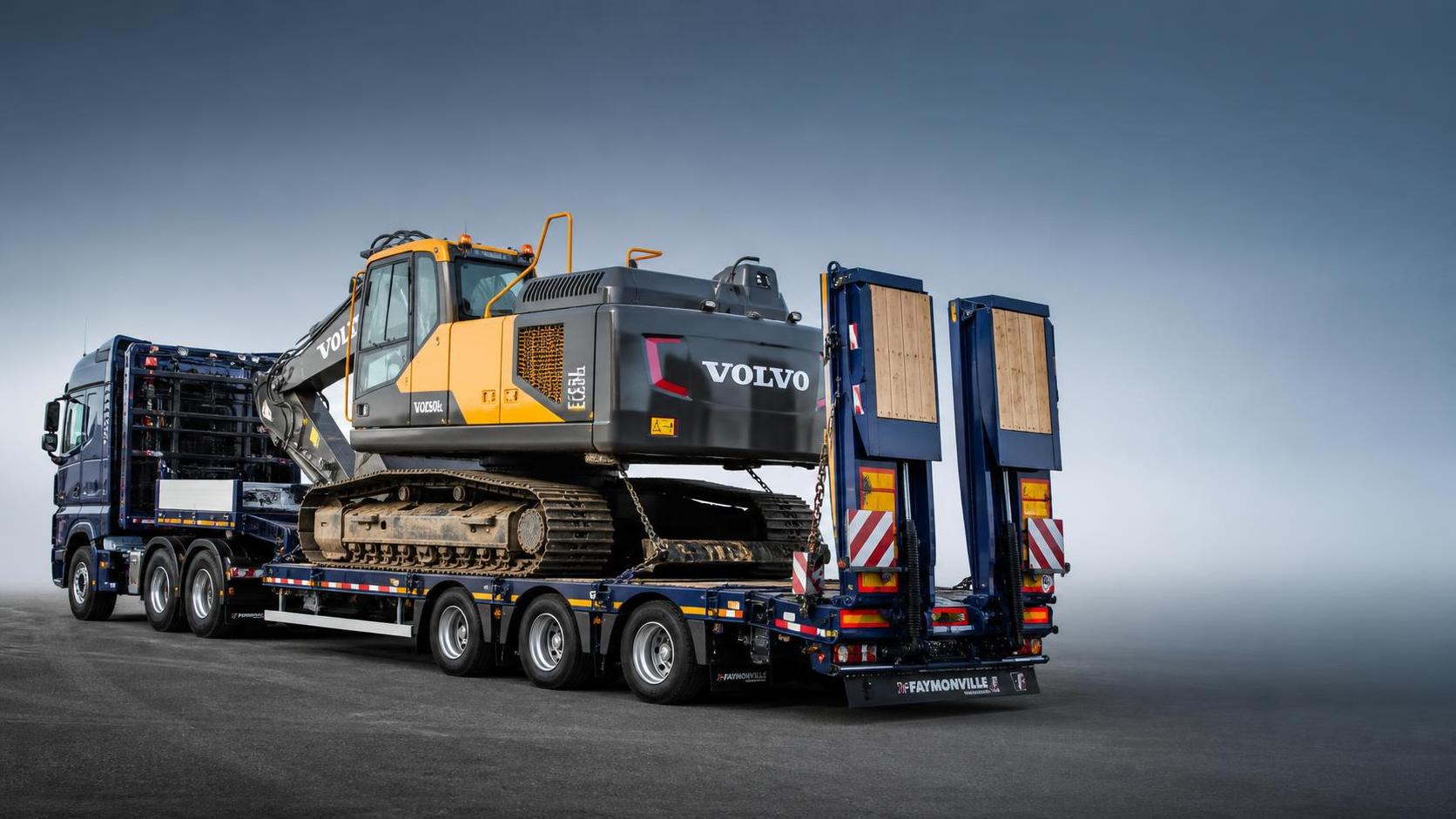
Payload rating, usable deck length, and axle arrangement are the three specification points that usually decide whether a flatbed semi-trailer will carry equipment safely or create avoidable transport problems. The basic question is not simply whether a machine can be loaded, but whether the loaded trailer can keep axle loads within local road limits, maintain stable weight distribution over rough surfaces, and give enough tie-down geometry for securement without forcing a poor machine position.
The advertised payload of a Flatbed Semi-Trailer is only a starting figure. In equipment transport, the practical payload is affected by trailer tare weight, deck construction, gooseneck design, axle spacing, tire rating, suspension type, and the weight concentration of the machine being moved. A compact machine with high operating weight may be harder on the trailer than a longer machine of similar total mass because the contact area is smaller and the wheel or track loads are more concentrated.
Payload Is About Distribution, Not Only Total Capacity
Many transport issues begin with a simple misunderstanding: a trailer may have enough nominal capacity for the machine, but the deck may not be designed for that machine’s point loading. An excavator, for example, can place high stress on localized track contact zones. A wheeled loader may put a heavy share of the load through two axles positioned close together. If the floor structure, crossmembers, and main beams are selected only by gross payload, deck fatigue can appear earlier than expected.
Structural details matter here. Common flatbed structures may use high-strength steel in the main longitudinal beams, with crossmembers arranged at intervals that balance deck stiffness and tare weight. When heavy equipment is expected, closer crossmember spacing, thicker deck plate in wheel paths, reinforced ramp transition areas, and stronger neck-to-deck connections are often more relevant than a broad payload number in a brochure. A trailer configured for palletized cargo may not tolerate repeated track loading in the same way as one intended for construction machinery.
Another frequent error is to calculate payload from machine operating weight alone while ignoring attachments, fuel, buckets, hammers, auxiliary tools, spare parts, dunnage, and chained securement gear. A machine that appears acceptable on paper can become overweight once the real transport condition is considered. If the attachment remains mounted, the center of gravity may also shift forward or outward, affecting kingpin load and axle load at the same time.
For repeated heavy moves, it is useful to review the following loading influences together rather than separately:
- The machine’s gross transport weight, including removable or fixed attachments
- Contact pressure and whether the load is applied through tires, steel tracks, or rubber tracks
- Deck reinforcement under the expected wheel path or track path
- Neck load transfer to the tractor through the fifth wheel
- Spacing between trailer axles, since this changes how load is shared across the axle group
A high-capacity trailer with a light deck build may still be a poor match for abrasive steel-track loading. By contrast, a slightly heavier trailer with stronger floor support can be the more durable choice when the same machine is moved repeatedly between quarries, earthworks sites, and road projects.
Deck Length Changes More Than Parking Space
Deck length is usually treated as a fit question, but in practice it changes balance, loading angle, turning behavior, and securement options. The usable deck length is more important than the overall trailer length stated in a catalog. Ramps, neck structure, rear overhang, toolboxes, side protection, and raised wheel areas can reduce the space that is genuinely available for a machine’s tracks or tires.
With short equipment, excess deck length can sometimes be managed by shifting the machine into the correct balance position. With long equipment, insufficient usable deck can force the machine too far forward or too far aft, pushing kingpin load or trailer axle load beyond a practical range. Either condition can affect steering axle loading on the tractor, braking response, and tire wear. Even if the machine physically fits, the final axle distribution may still be wrong.
Deck length also influences loading and unloading on uneven ground. A machine with low ground clearance, long wheelbase, or attachment overhang may contact the trailer during ramp transition if the approach geometry is too abrupt. This is not only an inconvenience. Repeated impact at the ramp hinge or rear deck edge can damage structural members over time. Longer, better-supported transitions can reduce this risk, especially for pavers, rollers, telehandlers, and machinery with low breakover clearance.
Some machines need space not because of body length, but because they must be positioned with the boom, arm, bucket, or counterweight in a transport-safe orientation. Excavators often travel more securely when the boom and stick are lowered into a supported position that helps keep the center of gravity low. If deck length is marginal, operators may be tempted to transport with an attachment angle that is less stable or harder to secure correctly.
Where several machine types are moved on the same trailer, a moderate increase in usable deck length can improve flexibility. That said, longer is not automatically better. Extra deck length adds tare weight, changes turning radius, and may reduce maneuverability in urban work zones, temporary site roads, or plant access areas. A longer deck can also make it harder to keep a short but heavy machine inside the ideal axle loading window unless the axle group and neck geometry are chosen accordingly.
Axle Setup Governs Compliance and Stability
Axle configuration often decides whether a trailer works well under real road conditions. The number of axles matters, but so do axle spacing, axle capacity, suspension type, and the relative position of the axle group under the deck. A two-axle flatbed may suit lighter machinery or more distributed loads, while heavier equipment commonly requires three or more axles to spread mass and reduce individual axle loading. The correct choice depends on the actual machine profile and route conditions rather than on a general preference for more axles.
Axle spacing changes legal load distribution in many jurisdictions. A trailer with the same total capacity can behave differently depending on whether the axles are closely grouped or spread farther apart. Wider spread may improve load sharing and road compliance in some cases, but it can also affect tire scrub during tight turns. Frequent turning in confined access areas can increase wear on tires, suspension bushings, and axle components, especially under high static loads.
Suspension selection is also practical, not cosmetic. Mechanical suspension may be simpler and more tolerant of rough conditions, but air suspension can offer advantages for cargo protection, deck height control, and ride quality depending on the machine being hauled and the route surface. For equipment transport, the question is whether the suspension maintains predictable behavior under concentrated loads and repeated loading cycles. A suspension well suited to general freight may not deliver the same durability when subjected to steel tracks, off-center loading, and frequent ramp operations.
For a Flatbed Semi-Trailer used in mixed engineering applications, axle setup should be considered with these real operating effects in mind:
- A larger axle group can lower the load carried by each axle, yet it increases maintenance points and may add tare weight that reduces net payload.
- Lift axles may help in some operating conditions, but they introduce another variable in maintenance and load management.
- Wheelbase and axle location affect how easily a machine can be shifted to achieve acceptable kingpin load without overloading the rear group.
- Brake balance across the axle set becomes more sensitive as load concentration increases, particularly when the machine is not centered exactly where the design assumes.
When heavy machinery is loaded slightly off-center to accommodate attachment clearance or deck obstacles, lateral balance becomes a concern. That can place uneven loads on suspension parts and tires across the left and right sides of the axle group. It may also reduce stability during emergency avoidance maneuvers or on roads with severe camber.
Material and Fabrication Details Affect Long-Term Suitability
Two trailers with similar dimensions can perform very differently if their material grade and fabrication quality differ. Main beams commonly carry the bending load, but local durability often depends on weld quality, gusseting near stress transitions, and the stiffness of crossmember-to-beam connections. Equipment transport creates repeated impact loads during loading, braking, and site-road travel. Poorly controlled welding heat, insufficient reinforcement around suspension hangers, or weak ramp hinge areas may not fail immediately, but they can shorten service life.
Deck material deserves more attention than it often receives. Timber decking may be practical for some freight, but concentrated steel-track use can crush, gouge, or loosen sections over time. Steel plate deck zones in track paths can improve resistance to localized damage, although they add weight and may become slippery if surface treatment is inadequate. A mixed deck arrangement is sometimes preferred when both machinery and general cargo are expected, but its usefulness depends on how the load is actually placed.
Fastener retention on bolt-on parts, protection of air and electrical lines, landing gear bracing, and ramp support structure all matter in day-to-day use. Trailers moving between paved highways and rough project access roads experience vibration that exposes weak mounting details quickly. A strong specification on paper can still underperform if small fabrication details are neglected.
Loading Practice Can Override a Good Specification
Even a correctly selected trailer can be compromised by poor loading practice. The machine should be placed according to actual axle readings or a proven loading reference for that specific combination. Visual estimation alone is unreliable, especially when machines have offset booms, rear counterweights, or attachments carried low over one end of the deck.
Securement layout must match the machine geometry. Tie-down points should allow direct restraint of forward, rearward, and lateral movement without relying on a single chain angle that looks tight but contributes little restraint in the direction that matters. Machines with articulated frames, oscillating axles, or free-moving attachments may require additional restraint points or blocking to prevent motion that changes load distribution during transit.
Ramp selection is part of the same technical decision. If ramp width, support, or angle does not match the machine’s track gauge or tire path, loading may introduce side loading into the ramp structure. Over time, this can distort hinges, damage support brackets, and affect alignment when the ramps are folded and secured.
Specification Mistakes That Lead to Rework
Some mismatches appear repeatedly in equipment transport. One is selecting a trailer by maximum machine weight and ignoring whether that weight is concentrated in a short footprint. Another is focusing on deck length without verifying where the axle group sits under the trailer. A long deck with the wrong axle position can be harder to load correctly than a shorter deck with better balance geometry.
A third mistake is treating all heavy equipment as similar cargo. A crawler excavator, a single-drum roller, and a wheeled loader may have comparable transport weights while imposing very different structural and balance demands. Steel tracks tend to punish the deck surface. Rollers may create intense line loads. Wheeled machines can shift dynamic loads under braking if not well restrained. Matching trailer configuration to equipment type is usually more effective than relying on a generic “heavy-duty” label.
Ground conditions at origin and destination should not be left out. If loading often happens on uneven aggregate, soft soil, or sloped temporary platforms, trailer torsional behavior and landing stability matter more than they would in a paved yard. In such cases, the strongest concern may not be highway travel at all, but the loading event itself.
Where machine transport is frequent, reviewing payload, deck length, and axle setup as a single system usually produces the clearest answer. Payload capacity tells only part of the story; deck length controls where the machine can sit, and axle arrangement determines whether that position can be used safely on the road. Once those three factors align with the equipment’s real dimensions, load concentration, and route conditions, the trailer is far more likely to perform consistently without repeated loading adjustments or premature structural wear.
Search Starts Here