
News
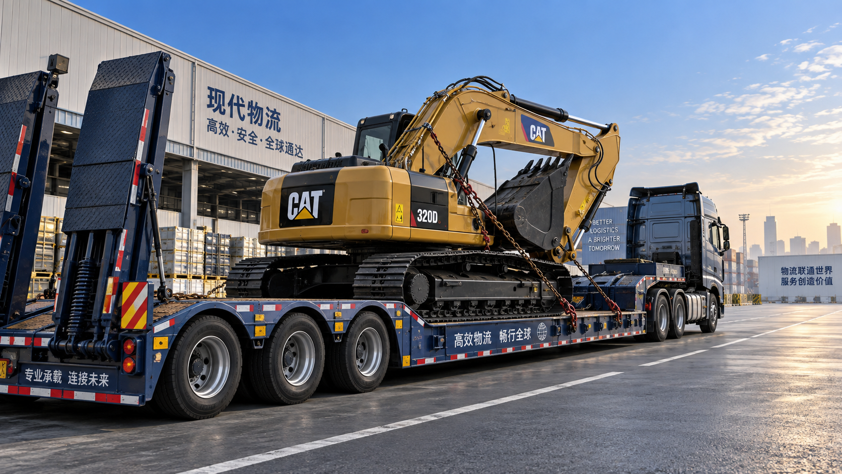
A low-deck trailer is used when equipment is too tall, too heavy, or too unstable to travel safely on a conventional flat platform. By placing the load closer to the road surface, the trailer reduces total transport height and lowers the cargo's center of gravity. That change affects clearance, stability, loading method, axle loading, and route suitability at the same time.
Tall equipment creates two separate transport problems that are often confused. The first is vertical clearance: the combined height of the trailer deck, machine, attachments, and securing hardware must pass beneath bridges, utility lines, tunnel entries, loading-bay roofs, and other fixed obstacles. The second is stability: a high center of gravity increases the overturning force during cornering, braking, lane changes, uneven-road travel, and loading. A lower deck addresses both, although it does not remove the need for careful load planning.
Why deck height changes the whole transport arrangement
Every trailer adds its deck height to the height of the equipment being carried. A crawler excavator, drilling rig, crane component, transformer, wheel loader, industrial press, or prefabricated machine module may already stand close to a route's available clearance. A standard flatbed can turn an otherwise manageable load into an over-height movement simply because the deck sits higher above the road.
A Low Plate trailer uses a lower central carrying area than a conventional platform trailer. The deck may sit between the wheel areas or be formed as a dropped section behind the gooseneck, depending on the design. This allows the main body of the machine to sit lower without requiring the equipment itself to be dismantled as extensively.
The height reduction is easy to understand in principle, but the real benefit depends on where the height is located. A machine with a tall cab, mast, boom pivot, exhaust stack, or lifting frame needs its highest point measured after it is positioned on the trailer. The top of the cargo is not always directly above the lowest part of the deck. Some equipment must sit farther forward or rearward because of axle loads, ramps, neck clearance, or the position of tracks and tires. As a result, the final transport height comes from the actual loaded configuration rather than the brochure dimensions of either the trailer or the machine.
Lower height also improves load stability
Reducing deck height lowers the center of gravity of the combined trailer and cargo. This improves resistance to side-to-side load transfer when the vehicle turns or travels on a cross slope. Heavy machinery is rarely a uniform block. Engines, hydraulic systems, counterweights, booms, batteries, gearboxes, and articulated structures concentrate mass in different positions. A machine may appear balanced when parked yet impose a strong lateral force during transport.
For tracked equipment, the benefit is often substantial because the machine can sit close to the deck across a broad contact area. Wheeled machinery requires more attention to suspension movement and tire support. Pneumatic tires can settle during a long journey, and air suspension on the trailer may change deck position when loaded or unloaded. The cargo should therefore be evaluated in its secured transport condition, not only at the point where it first enters the deck.
Lowering the equipment does not make an improperly secured load stable. Tie-down chains, binders, wheel restraints, blocking, chocks, direct lashings, and attachment restraints still need to control forward, rearward, and sideways movement. The trailer's lower profile reduces leverage, while the securing system prevents displacement. These functions complement each other.
Equipment shape determines whether a low deck is useful
Not every tall load benefits in the same way. The useful question is whether the tallest and heaviest portion can occupy the dropped deck area without interference. A compact excavator with the boom folded low may fit efficiently, while a machine with a fixed tall upper structure may still exceed clearance limits even on a lower trailer. Similarly, a crane attachment placed separately may change the height result more than the trailer selection itself.
A low platform can therefore solve the height problem while exposing another limitation. For example, a machine with low undercarriage clearance may scrape at the transition from ramp to deck. A long rigid machine may require a gradual approach angle that the available ramp configuration cannot provide. In such cases, temporary ramp extensions, detachable neck arrangements, or a different loading method may be more relevant than simply choosing the lowest possible deck.
Loading geometry is as important as carrying height
The route from ground level to the cargo deck has to be considered before loading begins. Ramps create an incline, and the trailer deck may include a breakover point where the angle changes. Equipment with a long wheelbase, a low bucket, a central undercarriage guard, or a low-mounted hydraulic cylinder can contact the ramp or deck transition even if its weight is within capacity.
Tracked machinery often climbs ramps differently from wheeled machinery. Tracks distribute force well over their contact length, but they can damage unsuitable deck surfaces and may lose traction on wet, contaminated, or smooth steel ramps. Wheeled equipment can place high point loads on narrow tires and can move unexpectedly if braking, steering, or drive control is not coordinated with the incline. Ramp surfaces, traction features, approach ground condition, and machine travel direction all affect the loading sequence.
Articulated equipment introduces another issue: its overall height can change during loading as the chassis pitches over ramps. A folded boom, mast, or attachment that clears when parked on level ground may rise during the transition. Clearance near the trailer neck, rear wheel area, or upper deck should be checked through the full loading path rather than only after the machine is positioned.
Weight capacity must be read as a system limit
Trailer capacity is commonly misunderstood as a single number. The usable limit is influenced by the structural rating of the deck, axle group capacity, suspension capacity, tires, wheels, coupling equipment, tractor configuration, and the distribution of the cargo. A trailer may be structurally capable of supporting a load while the actual placement produces excessive loading on one axle group or too little weight on the towing vehicle.
Heavy equipment seldom distributes weight evenly from front to rear. An excavator may carry a large counterweight at the rear; a loader may concentrate mass around the engine and articulation area; an industrial unit may contain a dense motor or transformer core away from its geometric center. Placing the equipment by visual centering can lead to poor axle balance. The load location should be based on known or estimated center-of-gravity position, trailer axle layout, and the permitted loading range of the complete combination.
Deck loading also matters at a local level. Steel crossmembers, timber decking, anti-slip surfaces, and reinforced load zones are designed for particular types of contact. A broad crawler track spreads load differently from a narrow steel wheel. Outrigger pads, machine skids, and sharp-edged support points may require suitable load-spreading material so that force is not concentrated into a small section of the deck.
Securement requires more than chains over the tracks
A heavy machine should be restrained against movement in every expected direction. The arrangement needs to account for braking forces, acceleration, cornering, vibration, road irregularities, and the tendency of some equipment to settle as suspension or tires respond to the journey. Securement points on the trailer must be rated and positioned so that the angle of each restraint produces useful holding force rather than only downward pressure.
Direct lashings from designated machine anchor points to trailer tie-down points are often used to resist fore-and-aft movement. Wheel chocks, track blocks, or fitted restraints can supplement them where appropriate. Attachments deserve separate attention. A bucket, blade, boom, fork carriage, removable counterweight, hydraulic tool, or detachable jib may move independently from the main chassis unless it is mechanically locked, supported, or separately restrained.
Parking brakes should not be treated as the primary transport restraint. They are designed to hold equipment at rest under defined conditions, not to replace a complete securing arrangement during repeated dynamic loads. Hydraulic systems can also lose pressure over time, so a raised attachment should not rely on hydraulic pressure alone to remain in position.
Route clearance is not limited to bridges
Height planning begins with the loaded measurement, but route evaluation should consider the full travel environment. Bridge structures are obvious fixed obstacles, yet lower risks may appear at utility crossings, site gates, toll areas, warehouse canopies, overhead signs, temporary construction barriers, tree cover, and road surfaces that rise beneath the trailer. A route with nominally adequate clearance can become restrictive where pavement crowns, steep approaches, or uneven access roads change the vehicle's angle.
Width and turning space also interact with a low deck. Equipment placed low between trailer wheel areas can improve height, but the machine's tracks, tires, steps, or side attachments may still extend beyond the available deck width. Wide cargo may require route controls even when total height is reduced. Long loads can sweep outward at turns, especially when the trailer has multiple axles or steering axles.
Ground clearance beneath the trailer should be reviewed alongside overhead clearance. A deeper dropped deck brings the cargo lower, but it may also reduce clearance at the underside of the trailer. Entering a steep yard, crossing a raised rail line, or moving over a sharp road crest can create a grounding risk. A low deck is most effective when the route and loading locations suit its geometry.
Common planning errors
- Using unladen trailer height: suspension compression under cargo weight changes the loaded deck position. The transport height should be measured after the equipment is fully placed and restrained.
- Measuring the machine in working configuration: mirrors, exhaust extensions, aerials, boom position, removable guards, and attachments can alter dimensions. Transport configuration must be clearly defined before route planning.
- Focusing only on gross weight: a legal-looking total weight does not confirm suitable axle distribution or deck loading.
- Ignoring the loading approach: a machine that fits on the deck may still be unable to reach it without interference at the ramps or deck transition.
- Securing the main machine but overlooking loose components: hoses, tools, detachable parts, and unsecured attachments can become hazards even when the chassis remains stationary.
Choosing the trailer configuration around the cargo
The useful configuration begins with accurate cargo information: overall length, width, loaded transport height, operating weight, estimated center of gravity, ground clearance, wheelbase or track length, contact points, and attachment condition. Photos and dimensional drawings can clarify shapes that are difficult to describe with one set of measurements, especially where a mast or boom extends above a narrow body.
Trailer design choices then follow from the limiting condition. A fixed low deck may suit equipment that is repeatedly transported in a similar configuration. A detachable-front or removable-gooseneck design can be preferable where direct drive-on loading and a lower approach angle are required. Extendable frames address length but introduce their own considerations for load placement and route maneuvering. Multi-axle layouts spread heavy loads, although their turning behavior and ground conditions need to be considered.
For tall and heavy equipment, the practical value of a lower platform is not merely a smaller height measurement. It creates more room to position the cargo within clearance limits, reduces overturning leverage, and can make a difficult load arrangement more manageable. Those gains are realized only when deck geometry, loading path, weight distribution, restraints, and route conditions are assessed as one connected transport task.
Search Starts Here