
News
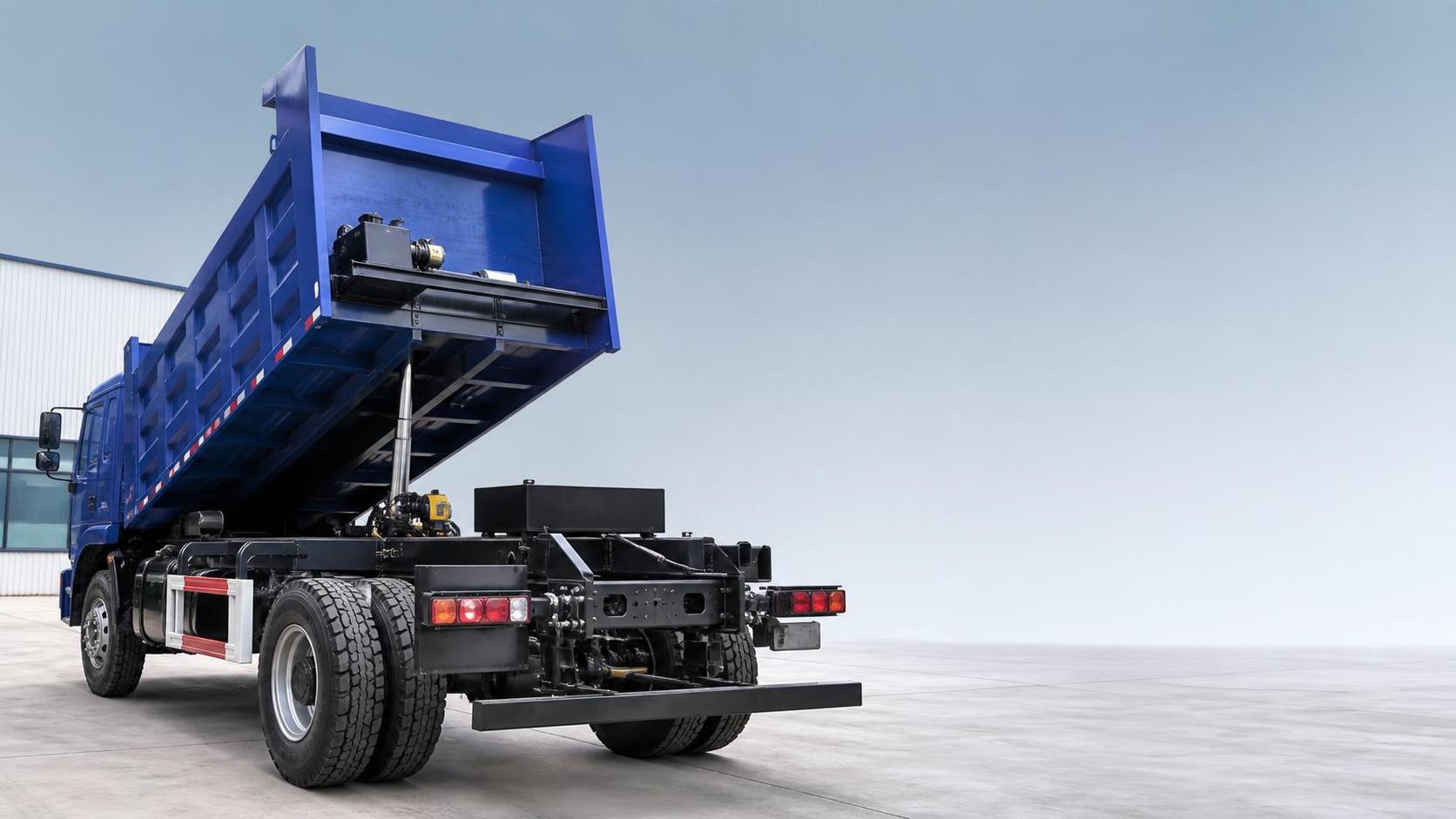
Ordering an engineering vehicle from a configuration sheet should begin with the working condition, not with the model name or the lowest quoted specification. A configuration list can contain many familiar terms, yet a small mismatch in axle ratio, frame section, tire type, hydraulic interface, or cab equipment may affect payload, fuel use, maintenance access, and delivery readiness after the vehicle reaches the jobsite.
The Cangshan Vehicle Configuration List should be read as a technical contract reference. Each line describes a physical component, a permitted option, or a boundary of supply. Read the document from the vehicle's operating task back to its core systems: load type, road surface, travel distance, climate, body or equipment installation, and maintenance conditions. This approach makes it easier to identify specifications that look acceptable individually but do not work well together.
Start with the vehicle identity and configuration scope
The first section usually identifies the vehicle series, drive form, wheelbase, cab version, chassis number range, and intended body arrangement. These details establish whether the listed components belong to the exact vehicle being ordered. A similar-looking model may use a different frame length, axle capacity, suspension layout, or electrical harness.
Pay attention to wording such as “standard,” “optional,” “available,” “prepared for,” and “excluded.” “Prepared for” normally means that mounting points, wiring, piping, or space may be reserved; it does not necessarily mean the final equipment is supplied or installed. An optional air-conditioning system, power take-off, fuel tank, spare wheel carrier, or hydraulic pump must be listed with a clear inclusion status. Do not assume an item is included because it appears elsewhere in a brochure or on a sample vehicle.
Where a configuration list shows a chassis only, separate the chassis scope from the body scope. A tipper body, mixer drum, crane, tanker, concrete pump, cargo box, or special-purpose superstructure may introduce additional requirements for subframe design, hydraulic power, electrical connectors, rear overhang, and weight distribution. The vehicle can be technically complete as a chassis while still requiring major work before it is suitable for its intended task.
Read dimensions as installation limits
Wheelbase is often treated as a simple length figure, but it influences turning radius, body mounting space, propeller shaft arrangement, frame deflection, and axle loading. A shorter wheelbase may suit confined sites and frequent turns, while a longer wheelbase can allow a larger body or more stable equipment installation. Neither choice is automatically preferable.
Compare the wheelbase with front overhang, rear overhang, frame usable length, and the proposed body dimensions. A body that extends too far behind the rear axle can increase rear axle load variation and reduce departure clearance. On rough work areas, excessive rear overhang may also expose lamps, mudguards, bumper assemblies, and hydraulic lines to impact.
Overall height deserves the same attention. Raised air intakes, roof-mounted equipment, beacon brackets, exhaust stacks, crane booms, and body covers can alter the final height after conversion. If the list gives only chassis height, obtain the completed-vehicle dimension separately. Access limits at workshops, depots, tunnels, ferry decks, or loading facilities can become relevant even where public-road travel is limited.
Match the chassis frame to the body and ground condition
The frame section is commonly described by rail dimensions, material thickness, reinforcement arrangement, and cross-member design. These figures should not be read in isolation. A stronger-looking frame is useful only when the suspension, axle capacities, body subframe, and mounting method are compatible with the intended loading cycle.
For repeated dumping, uneven haul roads, or frequent entry to construction areas, the configuration should show whether the frame has reinforcement in high-stress zones. Look near the rear suspension brackets, tipping pivot area, hoist mounting position, and body support points. A body installer may require a defined subframe thickness, longitudinal reinforcement, flexible mounting points, or restricted drilling zones. Drilling or welding directly on unsuitable rail sections can create corrosion points and stress concentration.
Frame-related entries should also be compared with the stated gross vehicle weight and axle loads. Gross vehicle weight is a legal and engineering limit for the completed vehicle, not a target payload. Kerb weight changes after the addition of a body, hydraulic system, toolboxes, protective guards, auxiliary tanks, and spare parts. Payload should therefore be calculated from the expected final weight rather than from an unbodied chassis figure.
Engine data needs an operating profile
Engine displacement, rated power, maximum torque, emission version, intake system, cooling arrangement, and fuel tank capacity all appear important, but their relevance depends on duty cycle. A vehicle travelling short distances at low average speed with repeated starts, steep ramps, or stop-and-go loading may require different torque delivery and cooling reserve from one that runs long highway sections.
Rated power is usually stated at a specified engine speed. Maximum torque may occur at a different speed range. Review both figures with the transmission ratios and rear axle ratio. High power alone does not show launch performance under load, gradeability, or the likely engine speed during normal road travel.
Cooling components deserve careful review in hot, dusty, high-altitude, or low-speed environments. Check whether the list identifies radiator capacity, fan type, intercooler arrangement, air filter configuration, and protective screens. In severe dust conditions, a two-stage or pre-cleaner arrangement may be relevant, but it should be confirmed as an actual installed configuration rather than treated as a general possibility.
Fuel tank material and capacity affect range, body packaging, and axle distribution. Aluminum and steel tanks have different protection and repair considerations. Tank placement must also leave clearance for body supports, hydraulic tanks, steps, battery boxes, and exhaust after-treatment components. If dual tanks are specified, confirm the usable capacity and whether both tanks feed the engine system.
Transmission, clutch, and power take-off must be considered together
The transmission line often shows the gearbox model, number of forward and reverse gears, clutch diameter, transfer case where applicable, and power take-off availability. Gear count by itself is not enough. The ratio spread determines whether the engine can remain in a useful torque range during acceleration, climbing, low-speed work, and road travel.
A close-ratio gearbox may support smoother progression on paved routes, while a wider ratio spread can provide lower crawl capability for heavy starts or rough terrain. The configuration sheet should identify the lowest gear ratio and the direct or overdrive top gear where those details are available. This makes it possible to assess the combined effect with the axle ratio.
For vehicles carrying hydraulic equipment, clarify the power take-off type before finalizing the order. Side-mounted, rear-mounted, transmission-dependent, and independent PTO arrangements have different installation and operating characteristics. The list should specify the PTO opening, rotation direction, output speed, torque capability, flange or pump interface, and whether the PTO itself is supplied. A gearbox described as PTO-capable may still need a separate PTO unit, pump, control valve, reservoir, hoses, and installation hardware.
Clutch specification matters when the vehicle will make frequent loaded starts. A larger clutch diameter does not automatically resolve a mismatch caused by an unsuitable first gear, overloaded body, or incorrect axle ratio. Confirm that the clutch rating and gearbox input capacity align with the intended gross weight and operating pattern.
Axles and suspension reveal the vehicle's real working limits
Axle entries normally include front and rear axle ratings, reduction type, differential lock availability, axle ratio, brake type, and sometimes hub reduction information. The listed rating must be read against actual axle loads after body installation. A vehicle can remain below its gross vehicle weight while exceeding one axle limit because cargo, equipment, water tanks, or a crane base is concentrated in the wrong position.
Axle ratio affects tractive effort and road speed at a given engine speed. A numerically higher ratio generally increases wheel torque and may suit lower-speed heavy-duty work, but can increase engine speed during highway travel. A numerically lower ratio may reduce cruise engine speed, yet it can make starts, gradients, and loose surfaces less suitable when fully loaded. The correct choice depends on tire rolling radius, transmission top ratio, expected travel speed, and terrain.
For multi-axle configurations, identify which axles are driven, steerable, liftable, or fitted with inter-axle differential locks. A 6x4, 6x6, 8x4, and 8x8 designation describes drive arrangement, but it does not fully explain traction hardware or suspension behavior. Confirm whether a lift axle is present and whether its operation affects body loading or stability.
Suspension specification should cover spring type, leaf count where stated, stabilizer bars, air suspension equipment, shock absorbers, and rubber bushes. Mechanical suspension can be suitable for demanding site conditions, while air suspension may be selected for particular transport or body requirements. The body manufacturer must know the suspension travel and chassis ride-height conditions so body-to-cab, tire-to-mudguard, and driveline clearances are maintained under full compression.
Brakes, tires, and steering should be read as a single safety system
The brake section may list service brakes, parking brakes, engine brake, retarder preparation, ABS, electronic stability functions, and air reservoir capacity. Confirm which functions are installed rather than relying on a generic safety description. Auxiliary braking can be relevant on long descents or with high gross weights, but its suitability depends on vehicle use, transmission arrangement, and local operating requirements.
Tire notation identifies width, aspect ratio, construction, rim diameter, load index, and speed symbol. A tire with the right rim diameter may still have an unsuitable tread pattern or load rating. Mixed-road, highway, traction, and off-road patterns behave differently on wet ground, soft soil, stone, and paved surfaces. Tire selection also changes effective rolling radius, which influences vehicle height, axle ratio behavior, and speedometer calibration.
Where dual rear tires are fitted, check spacing, mudguard clearance, and stone retention risk. Wide-base single tires can change weight, ground contact, and spare-wheel arrangements. The spare tire should be listed by size and rim type, especially when the running wheels use specialized off-road or tubeless assemblies.
Cab equipment affects usable working time
Cab entries often mix comfort features with operational equipment. Separate decorative options from items that affect visibility, fatigue, communication, storage, and daily inspection. Seat type, suspension seat adjustment, steering-wheel adjustment, cab tilt mechanism, mirror heating, windshield defrosting, air-conditioning, roof hatch, work lamps, reversing alarm, camera wiring, and fire extinguisher brackets should be recorded precisely where relevant.
Visibility equipment needs particular care when a body or rear-mounted machine changes the original sightlines. Confirm mirror arms, rear-view camera provision, side marker lamps, work lights, and harness connections against the completed vehicle layout. A camera listed on the chassis may need relocation after body construction.
Cab color, trim, sleeper arrangement, and infotainment details are usually lower priority than electrical capacity and service access. Still, any selected cab version must fit the route and work pattern. A high-roof cab, roof air deflector, or external sun visor can affect overall height and access clearances.
Resolve options before the document becomes an order reference
Configuration lists sometimes contain several alternatives separated by slashes, brackets, or option codes. These are not interchangeable descriptions. Each unresolved alternative should be converted into a definite order statement with a part description, quantity, fitment position, and inclusion status.
- A listed “air-conditioning option” should identify whether the complete system, compressor, controls, refrigerant charge, and cab wiring are included.
- For a PTO-related entry, record the gearbox opening, PTO unit, hydraulic pump, tank capacity, hose routing, control method, and body-builder responsibility separately.
- Where a differential lock is shown, clarify whether it is an inter-axle lock, cross-axle lock, or both, because the operating effect is different.
- “Export equipment” should be broken into actual items such as warning triangles, tool kit, speed limiter setting, language labels, or protective packaging when these are required.
Use the final configuration as a controlled reference during chassis inspection, body installation, documentation preparation, and handover. Any late substitution should be evaluated for its effect on dimensions, weight distribution, electrical compatibility, spare parts, and service documentation. A clear, line-by-line record prevents a configuration list from becoming a collection of assumptions after production has started.
Search Starts Here